
- Home
- Products
-
-
Solids Control Equipment
- Linear Motion Shale Shaker
- Decanter Centrifuge
- Mud Cleaner
- Vacuum Degasser
- Centrifugal Pump
- Shear Pump
- Submersible Slurry Pump
- Mud Agitator
- Mud Gun
- Jet Mud Mixer
- Desilter
- Water Tank
- Mud Tank
- Diesel Tank
- MD210 Drilling Mud Cleaner
- Balanced Elliptical Motion Shale Shaker
- Oilfield Drilling Mud Desander
-
Solids Control System
- Drilling Mud Cooling System
- Solids Control System
- Mobile Solids Control System
- Arctic Solids Control System
-
TBM
- Tunnel Boring Mud System
-
HDD
- HDD Mud Recovery System
-
-
- News
- Services
- Marketing
- About Us
- Contact Us
- Videos
Home > KOSUN News >
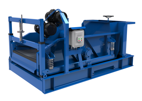
The Installation Steps of KOSUN LS584 Series Shale Shaker
Feb 05, 2024
This article is about the installation procedures for KOSUN LS584 Series Shale Shaker. KOSUN LS584 Series Shale Shaker is shipped fully assembled and no additional assembly is required.
Safety
Pay particular attention to information concerning lifting points and the use of a spreader bar in Chapter VI before lifting or moving the equipment.
Installation Sequence
Following is the sequence of steps for installing KOSUN LS584 Series Shale Shaker. The sequence presented may vary depending on selected options, the users’ facilities, and previous experience with this type of equipment.
1. Position and level equipment at the installation site.
2. Connect mud feed lines of adjustable flow to the feeder of the shale shaker.
3. Examine and ensure cross support and side support are reliably installed at corresponding positions, Examine and ensure the screen is installed levelly and evenly with appropriate tensioning degree.
Required Clearances and Positioning
Sufficient space should be provided around the equipment to facilitate access for maintenance, inspection, and adjustment. The recommended clearances between the shale shaker base and its peripheral barriers are 2.5ft (760mm).
Typical operation and maintenance functions include, but are not limited to, the following activities:
1. Change cross support, side support and screen.
2. Adjust the angle of the screen frame.
3. Connect, adjust and disconnect the mud feed lines of adjustable flow.
Equipment Leveling
To ensure even distribution of feed slurry across the screen panels, the shale shaker must be properly leveled. Leveling must be along the length and width of the unit. A 4-foot level is recommended to check the level.
Non-compressible shims should be used as required to level the machine.
Electric Power Connections
Connect the facility's electrical power supply to the junction box by the wiring schematic. The rotation directions of two vibrating motors of new equipment do not need to be adjusted.
The vibrating motor is a three-phase, 50 or 60-Hz motor. The motor must be operated at the design voltage. For motor power requirements, refer to the label on the motor data plate.
Warning! The vibrating motor must be operated at the designated supply voltage.
Warning! High voltage may be present. Lock out and tag out the power supply to prevent accidental application of power while making electrical connections.
Warning! Electrical connections must be made by the National Electrical Code (NEC) and all applicable local codes. Failure to comply may result in an unsafe condition that could injure personnel or damage equipment. Ensure that all electrical and conduit connections are secure.
